Ursus: model rocket with thrust vector control
August to December 2024
After taking Applied Physics at UC Berkeley’s Academic Talent Development Program (Summer 2024, a year after taking their Electronics Lab), I was interested in building something “dynamic”. I had been watching rocketry videos for a while, which I found exciting. I decided to build a thrust-vectored rocket after seeing a video by popular YouTuber BPS.space.
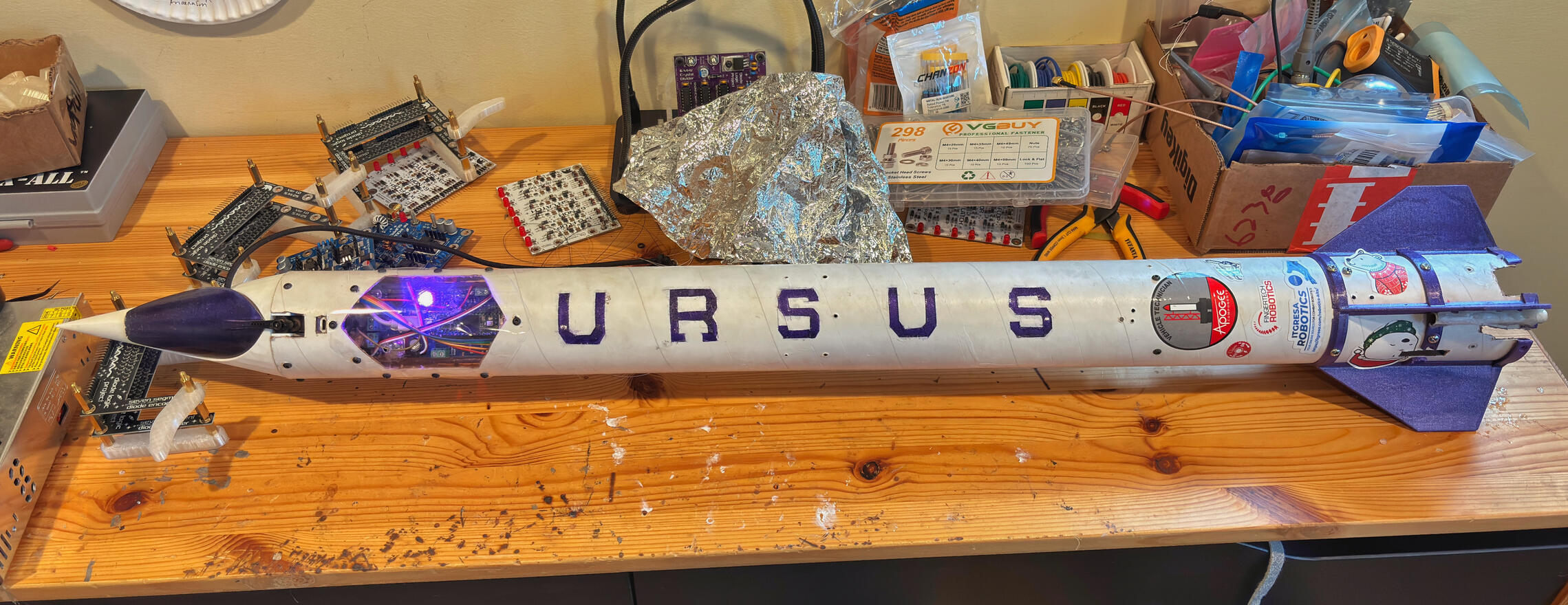
Ursus's first flight after 4+ months of development. My grand-uncle's farm has a nice open field which he let me use for the launch. Ursus recovered successfully.
~December 22 2024
1. Ursus Mechanical Design
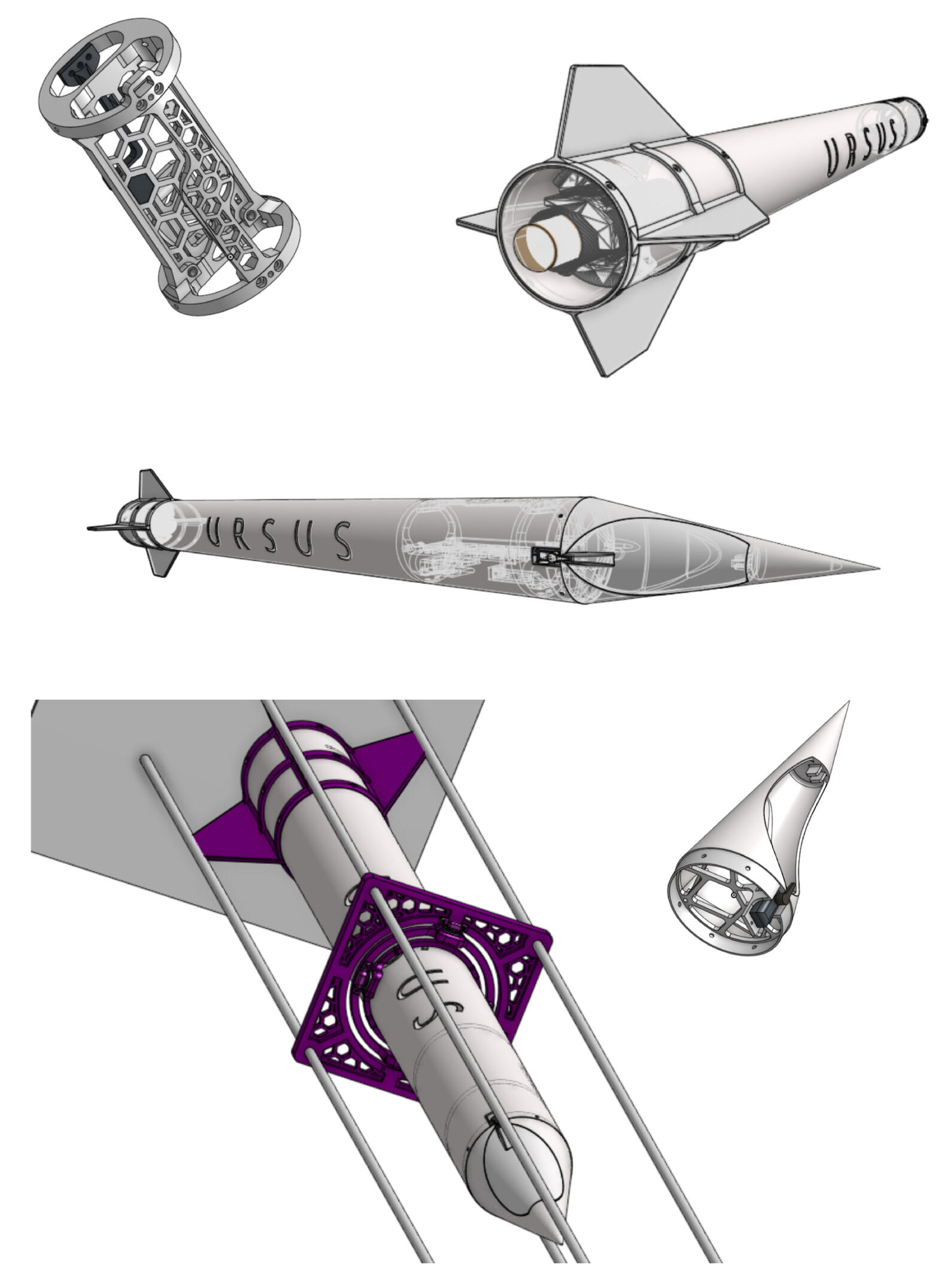
I designed my own avionics bay and nosecone. Instead of a traditional ejection-charge parachute deployment, I decided to use a servo and the help of gravity to release my parachute from the nosecone at apogee (an idea I took from Air Command Rockets’ “Nova Water Rocket”). I used the thrust-vectoring gimbal from BPS.space for active stability, and added fins for passive stability. Bottom left is the gimbal for the whole rocket that allowed me to test the control algorithm using a drone prop.
~August to September 2024
2. Ursus Flight Computer + Avionics Bay
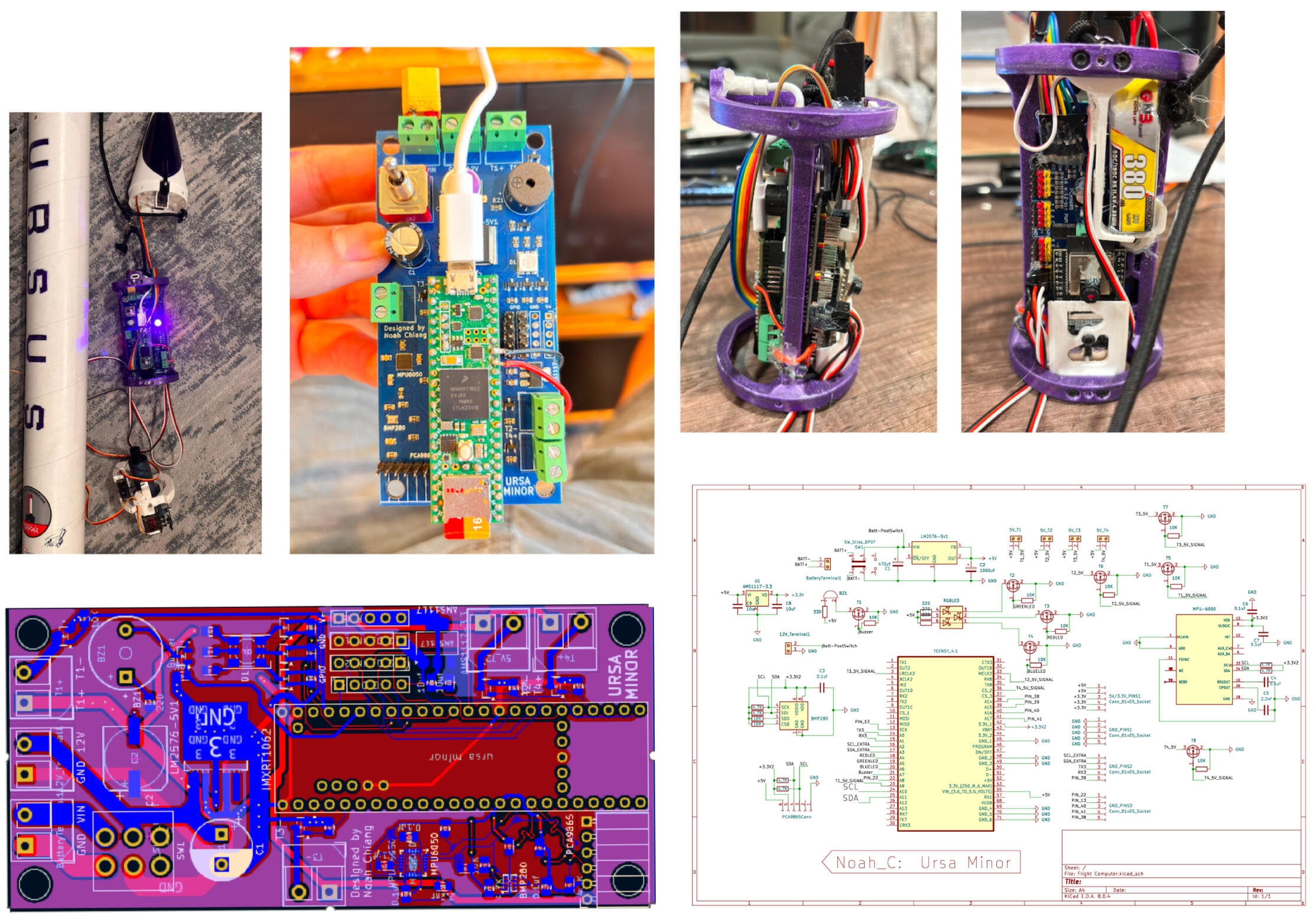
I started my flight computer with the help of BPS.space tutorials. My version has some slight changes: a Teensy 4.1 instead of 3.6 and an MPU6050 IMU instead of BNO055. I also added a servo driver to save the Teensy the task of sending PWM signals to the various servos. Capturing onboard video was a priority: I added an ESP32 camera module, which doubled as the rocket’s point of communication with the ground station. The Teensy conveniently has an SD card slot for data storage.I had accidentally designed the PCB to use a switching 5V regulator instead of a linear regulator, so I never added an inductor. This caused the Teensy to randomly turn off for a few weeks until I discovered the problem and replaced it with an external voltage regulator IC. I had also used the wrong pins for I2C communication because of an inaccurate KiCad symbol, which I fixed by carving out traces and wiring externally. I used purple spray paint to decorate Ursus and the avionics bay.
~September 2024
3. Ursus Flight Simulation and Code (OpenRocket, MATLAB, C++)
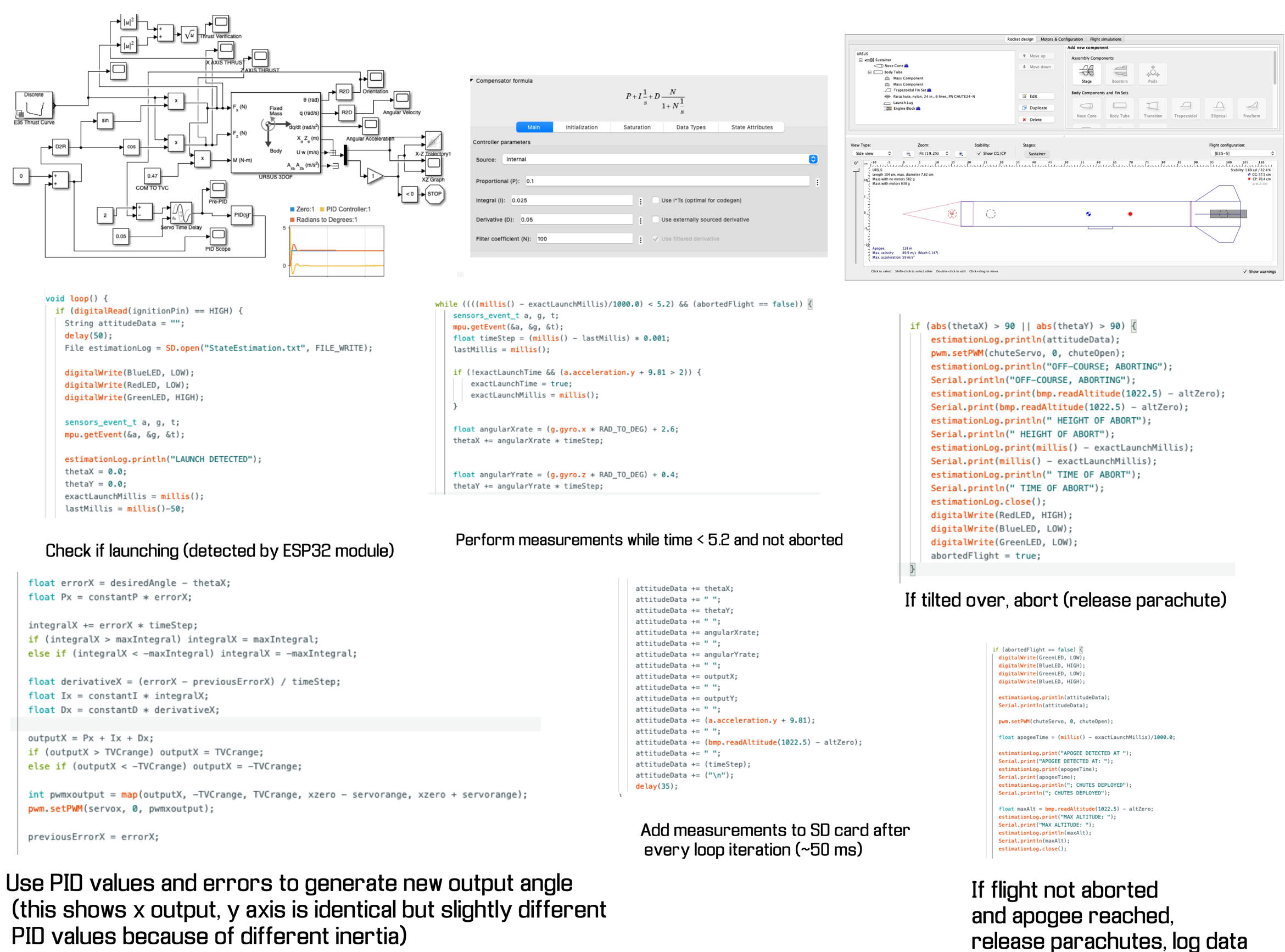
BPS.space introduced me to OpenRocket (top right). I used it to find the best mechanical parameters for Ursus: nosecone and fin shape, body tube length, and avionics placement. OpenRocket predicted a 128m apogee around 5 seconds after launch and a max acceleration of almost 6 G’s using an E-35 Questjet rocket motor.BPS.space also showed me how to use MATLAB’s Simulink tool (top left) to tune PID values for the control algorithm. Plugging in my rocket’s moment of inertia (obtained through hanging tests), mass, and the E-35 thrust curve allowed me to simulate flights in X and Z space. I added a servo time delay function to make my simulation more realistic.I coded the Teensy in the Arduino IDE. The main loop checks to see if the ESP32 camera module received a signal to launch (over ESP-NOW) before starting to measure angles and stabilize the rocket (waiting until launch to start the IMU reduced sensor drift). I spent weeks refining and testing my code.
~October to November 2024
4. Ursus Thrust-Vectoring Activation Demo; In-Gimbal Testing
Part I (00:00-00:07): The red light at the start is the calibration phase. This was in response to IMU drift encountered while testing, which I solved by starting the IMU and setting the current orientation as the new “zero” right before simulated launch. After 5.2 seconds (number obtained via OpenRocket), the green light turns to blue, signifying apogee.Part II (00:08-00:21): My friend Jack helped during this drone prop test. The reason Ursus isn’t straight up is because we wanted to test Ursus’s ability to hold a direction. We set that tilted position as the “zero” and maintained it. I made sure to use different PID values obtained from MATLAB by plugging in the lower thrust of the drone motor (around 20N, measured using scale). The fins aren’t on because they interfere with the gimbal, so I added an equivalent weight ring around where the fins’ center of mass would be (in black). Gimbal testing was invaluable for debugging and ironing out code.
~November 2024
5. Ursus Flight Analysis
Most of the flight went smoothly: the weather was clear, I was able to communicate remotely with the rocket and the igniter (separate ESP32 triggering ignition circuit next to launch stand), and Ursus was able to correct against the wind using my thrust-vectoring algorithm.What was unexpected was Ursus’s parachute waiting until the last moment to unfurl. I know from my flight log (next slide) that the parachute deployed at apogee. My hypothesis is that the Mylar parachute, which I had folded the night before, was too tightly packed inside the nosecone. I had meant to repack it an hour before the launch, but forgot. Nonetheless, the ejection charge of the rocket motor (set to go off after ~11s) shook Ursus right before it hit the ground, allowing the parachute to unfold. Ursus was recovered unharmed, but it was a crazy close call.
~December 22 2024
6. Ursus Data + Other Pictures
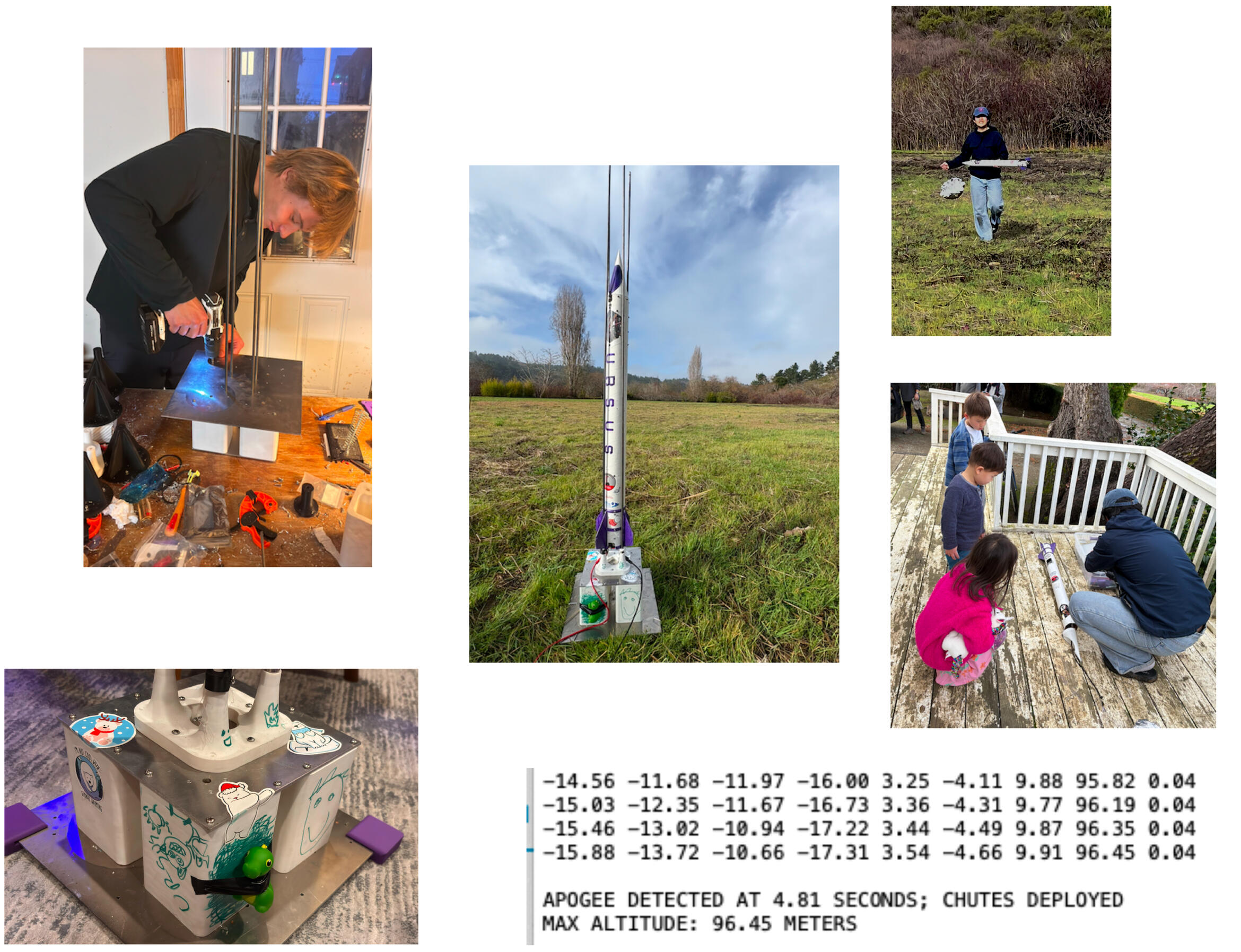
Immediately after Ursus landed, I sprinted over. I remember having mud all over my pants, but being pumped after seeing Ursus and its data were safe. The flight data at apogee (bottom right) shows a measured max altitude of close to 100m, below the OpenRocket 128m estimate. Apogee occurred at 4.81 seconds, which is when the parachutes deployed. This was earlier than the OpenRocket estimate of 5.2 seconds, but predicted by a pressure sensor in the flight computer, which observed the increase in altitude start to slow. The parachute would've deployed at 5.2 seconds regardless.Standing top left is my friend Alex Bozinovic, who helped me assemble a base I designed out of sturdy aluminum, steel guide rods, and 3D-printed supports. I had scouted the launch location previously, noting that I could use tent stakes to hold the base sturdy. Above bottom right contains some curious extended family members who showed up to watch the launch.
~December 2024